Panduit Wire Terminations Dialog
Lets you to format and create the final Wire Termination report output that will include the termination information.
Accessed when:
- You select the Output button in the Wire Terminations dialog.
The Panduit gauge check program will read your connection list and based on maximum and minimum gauges entered into your parts database, it will report any wires that are oversized or undersized.

Create Tab
| Setting | Description |
|---|---|
| Output rile | Enter the path and filename for the output file that will be created by the export tool. |
| Output format | Enter the path and filename of a formatting file that specifies the structure of the export file. A large variety of formats are possible. |
| Header file | Enter the path and filename for the header file. A header file is a text file that serves as a heading to create column names in the output file. |
| Gauge Check |
Reads your connection list and based on maximum and minimum gauges entered into your parts database, it will report any wires that are oversized or undersized. This can be especially useful for catching sizing errors on devices like fuses or motors which have a minimum gauge requirement or component that have a physical limit on wire size. For this function to work properly you must have the connection point texts for all of your parts entered into the parts database and the Gauge range. The file will display any wires listed in the shortest distance connection list that are outside of the range specified in the parts database. If connection point data is missing from the parts database it will also display an error. |
| Assign Terminations | Creates an MDB file of the assigned connection information. This file is created as an intermediate step so that you may manually or automatically modify the results before the final output. |
| Update BOM | Sends all of the assigned terminations to the project's Bill of Materials. Any terminations previously written to the project are first deleted. |
| Post Process | Allows you to write custom code to manipulate the Access database used to temporarily store the connection information. Selecting this button will run any EXE file named POST_PROCESS.EXE, which must be created by the user and placed in the PanduitDataEditor folder inside the Plugins folder of your Substation installation. |
| Create | Creates the specified output file. |
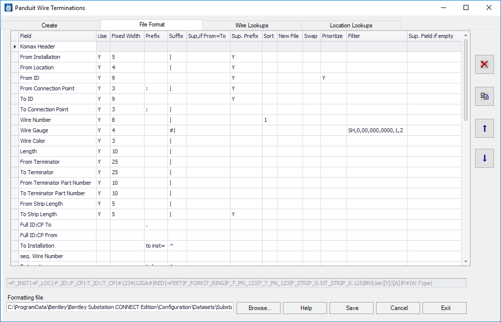
File Format Tab
The File Format tab is used to structure and filter the information in the exported file. The formatting tool allows you to select all of the connection information from Substation and place it into a file in the format that you need. The tool will allow for creation of comma-separated files, fixed field width files, XML files, INI files and many other formats. It will also provide lookup capabilities. For example, a spool number can be assigned to a wire based on its gauge and color.
The tab is used to format the information for one wire. When the output file is created, the format is used over and over for each wire. The dialog also allows the user to filter out certain wires or to have them sorted with up to 15 nested sorts.
Select each variable and use the up and down arrow buttons to put the variables in the order needed for the export file. A line at the bottom of the dialog displays a sample line of output.
Wire Lookups Tab
The Wire Lookups tab enables you to assign new values to wires based on existing values entered into Substation. This could be done to select a wire number based on gauge and color or a strip length based on wire gauge.
Lookup values allow you to specify values in the export file based on a combination of wire variable. For example, a color and gauge can be used to specify the part number for a specific wire spool. The gauge can be used to specify the wire diameter. This avoids having to fill these values into the wire attributes on every wire. However, if the values cannot be determined from a simple lookup, you may need to use wire attributes and place data on every wire. For example, if you require Outside Diameter and you are using two different types of wire, Gauge alone would not be enough to determine the correct diameter to use. You would have to use one of the wire attributes to specify wire type, when you create your schematics.
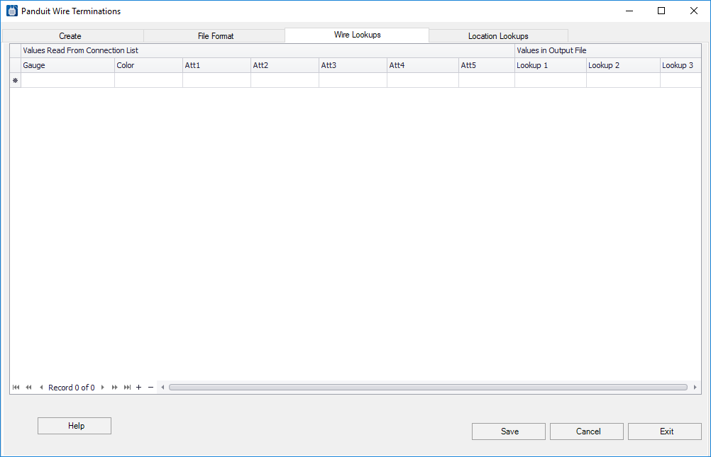
| Setting | Description |
|---|---|
| Lookup 1 | Enter the values and the corresponding wire attributes. |
| Lookup 2 | Enter the values and the corresponding wire attributes. |
| Lookup 3 | Enter the values and the corresponding wire attributes. |
| Save | Saves the changes. |
Location Lookups Tab
The Location Lookups tab allow locations to be sorted in a non-alphanumeric sequence. Location Lookup Values allow you to modify sorting based on location. Normally all sorts are alphanumeric. If you have set location names and want to create wires in a non-alphanumeric sort, by entering lookup values for the set location names a non-alphanumeric sort can be achieved. For example: locations could be named for sub-panels within the enclosures. The locations names may be TOP, LEFT, MAIN, RIGHT, DOOR, and BOTTOM. With a normal alphanumeric sort the wires would be sorted in the order BOTTOM, DOOR, LEFT, MAIN, RIGHT, TOP. If users want the wires for the Door to be listed first and then the main panel, they can enter the location names in the Location Lookup dialog and enter a lookup value of A next to the DOOR and B next to the MAIN, etc. The wire sort will now list wires in location DOOR at the top and then location MAIN.
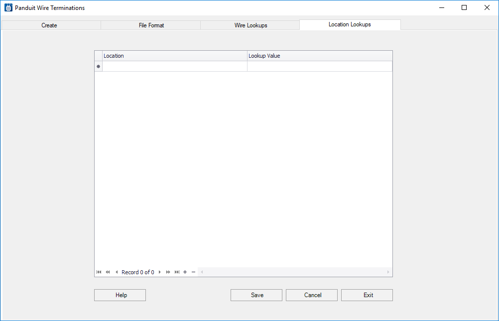
| Setting | Description |
|---|---|
| Location | Enter the names of the locations. |
| Lookup Value | Place letters that when sorted alphanumerically will put the corresponding locations in the desired order. |
| Save | Saves the changes. |